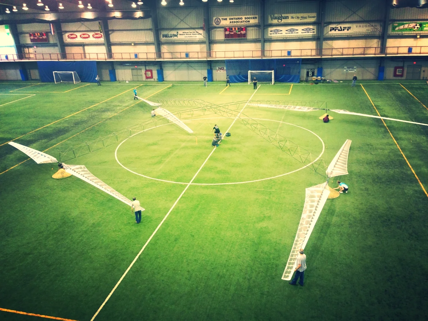
The crucial rotor design of the Atlas human-powered helicopter was completed by the end of April 2012, and construction began with the full student team in May. The initial configuration study resulted in the selection of a quad-rotor design similar to that of the Yuri I (Japan) and the Gamera (USA) human-powered helicopters. This was based on a lower predicted power requirement, the stability of the configuration, and the ease of construction based on many parts with production-line repeatability.
The rotor optimization was carried out using the in-house computational model outlined below. Further design on the helicopter components and overall structure was done using in-house finite element analysis programs and further computational optimization, as well as empirical design-test processes.
Many changes were made throughout the flight testing process, but the overall size and weight remained nearly the same.
Rotor Radius: 10.2m (33.5ft)
Maximum Dimension: 46.4m (154ft)
Height: 3.7m (12.1ft)
Overall Weight: 55Kg (121.4lb)
Computational Modelling and Design Optimization
The computational model involves a medium-fidelity aerodynamic model, combined with a finite-element structural analysis. Given a set of roughly 30 design variables, including rotor geometry, lift coefficient, spar diameter, and tube thickness the program computes the total mass of the aircraft, the required flight power and the stresses in all the various components. A gradient-based computational optimizer is then used to determine the design that minimizes the required power. Success of this design strategy depends on the accuracy of the aerodynamic model and structural predictions.
Several low and medium fidelity aerodynamic models have been implemented, including a simple momentum theory model, a blade-element model and a discrete vortex-ring model. The more advance vortex-ring model has the capability of computing the airflow pattern through the rotor in close proximity to the ground. Modelling this “ground-effect” is essential to the design of a helicopter that operates at such low altitude. The animation below shows the induced flow pattern as computed by the vortex-ring method. The graph shows how the induced power is reduced in proximity to the ground, where h/R is the fraction of the height to the rotor radius. The results of the vortex model are plotted along with empirically derived models given by several other authors.


The fraction of the induced power in ground effect to the induced power in free hover is plotted. "Vortex HF, MF and LF" represent high, medium and low grid resolution in the calculations.
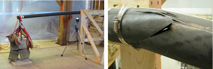
The structural model is a linear finite-element model based on classical engineering beam theory. Composite analysis methods are used to generate accurate structural properties and failure characteristics of the carbon fibre tubes. During the course of the human-powered ornithopter project extensive structural testing was performed on representative tubular specimens in order to fine-tune the model. This gave us the capability, at the outset of the project, of predicting structural deformation and failure to within 5% accuracy, resulting in a structure that is only just as heavy as it needs to be. The image below shows structural failure testing during the summer of 2009.
Finally, a gradient-based optimizer is used to navigate the design space and find a solution that truly results in minimum required power. The optimizer is able to evaluate the trade-off between the benefit of extra rotor diameter and the extra structural weight, or the benefit of wire bracing versus the extra aerodynamic drag, all while considering the aerodynamic efficiency and nearly a dozen different failure modes. The combined aero-structural model can evaluate a complete helicopter design in 0.1 to 15 seconds depending on the fidelity of the chosen model. This allows rapid design optimization that can be completed on the order of minutes instead of days.
Construction Techniques
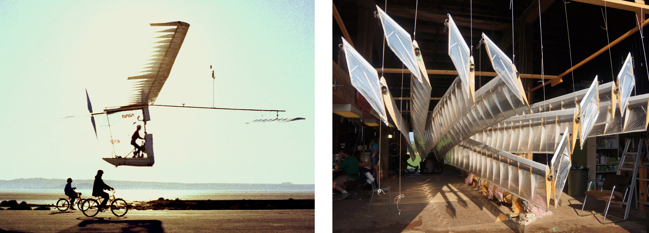
The rotors were constructed in a similar fashion to those of the Gossamer Albatross, a human-powered aircraft that crossed the English Channel in 1979. The main spar is a carbon fiber tube, whose structural weight is reduced through the use of wire bracing to share the lift loads. The airfoils are constructed with expanded polystyrene foam with balsa wood cap strips on the top and bottom. The rotor is then covered with an incredibly thin sheet of Mylar plastic film, making the whole rotor transparent. The images above show the structure of the Atlas rotors along side the Gossamer Albatross.
Power Plant

Maximum human power output (NASA 1964). The "First-class athletes" curve is slightly out of date, and these days many athletes include our pilot Todd Reichert can exceed the curve.
Todd Reichert was the pilot selected to fly the Atlas. Todd was a national-level speed skater and competitive athlete in the world of human-powered streamlined vehicles. His piloting background, as well as his experience flying the Snowbird human-powered ornithopter made him well suited for the job.
At the time Atlas was designed, the average power required for a 1 minute Sikorsky Prize flight estimated at 550 Watts for an 80 kg pilot like Todd. At 772 Watts for 1 minute, our pilot’s power output exceeded the power requirements of the helicopter by a safe margin. The predictions would have been more accurate if the helicopter could descend faster without entering a fatal vortex ring state, by in the Todd had to spend a lot more time at altitude and the average power for the flight ended up being just over 700 Watts.