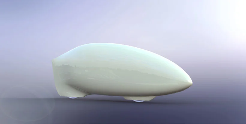

After years of dreaming about the ultimate bicycle, AeroVelo is excited to finally present Eta: a two wheeled-speed demon designed to significantly surpass highway speed limits on less than one horse power and to break the current land-speed record of 133.8 km/hr. Eta builds off of last year’s Bluenose design (which reached 125.0 km/hr) with several similarities and many key differences. Once again the bike has no windscreen and instead uses a tiny camera on the top of the bike to provide the pilot’s vision. Designing with this in mind Eta is able to achieve a significantly more advanced aerodynamic shape. The next biggest difference comes in the form of wheels, where we’ve now moved up from the small 406 tires (roughly 20 inch) to a more standard 650C (roughly 26 inch). This makes clearances a lot tighter and limits steering to pretty small angles, but the gains in rolling resistance may be substantial. Beyond what you can see in the diagram below, there’s an array of improvements in every category. Read on to find out, first of all, why these bikes go so fast, and second, what the strategy is for the new design.
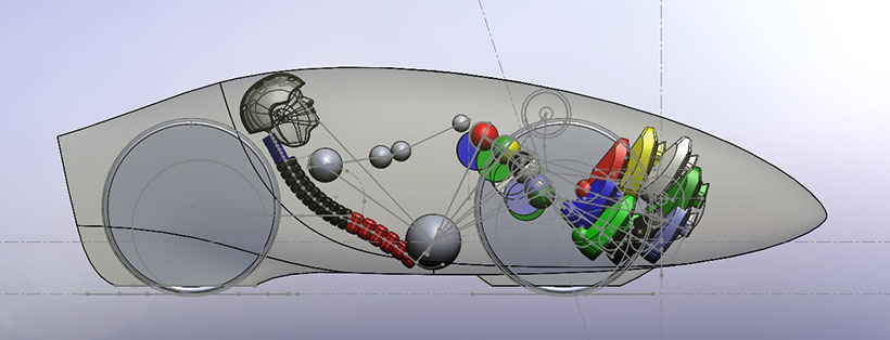
Layout of the new bike, showing pilot position and wheels, with sketches of the steering axis and intermediate drive location.
Why do these bikes go so darn fast?!
People always ask us what makes these bike do what they do. Is it the gears? Is it some magic drive mechanism? No to both.
Really, it all comes down to efficiency, which is actually the reason that the bike is called Eta. Eta is the greek letter often used in engineering as the symbol for efficiency (Yes, thank you, we are aware that we are a team of nerds). Efficiency is about reducing or eliminating the forces that are resisting our forward motion. In the case of a bluff body, like a cyclist or a car, the aerodynamic forces at high speeds are huge. By streamlining the body (ie. making a smooth contour with no massively separating turbulent vortices) we can reduce the aerodynamic forces by about 20 times. All of a sudden, with the aerodynamic forces drastically reduced, all of the other little forces become a much bigger percent of the total equation. Effectively, once you’ve got a streamlined body, every little thing matters all that much more. Rolling resistance, the smoothness of all the bearings, the drag on the wheel spokes and the chain efficiency all become highly significant. So our first objective in is to isolate all the factors that can make us go faster, and quantify the order of importance.
Below is what we call our Design Derivatives which quantifies how much faster we will go with a given change in a certain metric, based on our simulations of a speed run at Battle Mountain:
- P (Pilot power): 1% change = 0.49 km/hr
- Eta_drive (Chain Efficiency): 1% change = 0.49 km/hr
- CdA (Aerodynamic Drag Area): 1% change = 0.28 km/hr
- Crr (Rolling Resistance): 1% change = 0.13 km/hr
- M (Bike Mass) 1% change = 0.03 km/hr (0.07 km/hr if the mass is rolling with the rim of the wheel)
So what’s the design strategy?
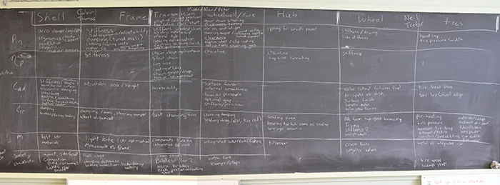
We’ve started by breaking up the design into a series of sub-components, and for each sub-component we brainstorm how it can be designed to improve each of the metrics in the list above. The result of our first brainstorming session was an awesome design matrix with loads of ideas for improving each system in some ways that we hadn’t fully considered before.
We then split the team into several sub-teams, each tasked with a set of design objectives:
Structural Design: Calvin, Thomas and Cameron will be leading the structural design of the shell and frame. This year, the aerodynamic shell and the structural frame underneath will be separate components. The shell splits in half at a position that has the smallest possible impact on the aerodynamics (just after the transition point). The frame is then being optimized for structural stiffness and pilot ergonomics (for better power delivery), as well as other considerations like an adjustable steering geometry or different styles of drive systems. The images below show two possible configurations for how the structure splits to go around the pilot’s head and down to the wheels, and how it connects to the intermediate drive above the wheel.

Initial configuration options for bike frame structure.
Drive System: Marc, Alex and Peter are leading the complex design of the drive system from the cranks, through the intermediate drive to the wheel. Oh, yes, and the brakes too Designing a fast bike means designing a small bike, and the biggest thing we learned the years we’ve been to Battle Mountain was the importance of the clearances around the drive train, the wheel and the pilots legs/feet. Nothing has more than a few milimeters of extra space, which makes for a really fun multi-component design challenge. Below is a schematic of the front hub, showing the integration of the disk wheel with the freewheel, wheel enclosure (wheel well) and axle. Besides the clearances, the most important part of the drive train is the efficiency: the length of chain, alignment of chain, bearings, tensioners, derailleur jockey wheels all have an impact on how much of the pilot’s power makes it to the road!
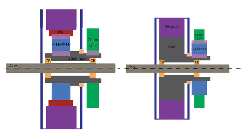
Schematic diagram of the configuration option for the front hub: a complex piece that integrates a freewheel, cog, and a method of aerodynamically sealing the wheel enclosure.
Wheels and Tires: Trefor and Neil will be taking the lead on anything that rolls. This involves the rolling resistance of the tires as well as the aerodynamics of the wheels themselves. For improved rolling resistance we’ve moved up to 650C tires, which gives less resistance first because of it’s size, but also because it gives us access to all of the best technology that goes into making full size bicycle racing tires. This involves better rubber and high-pressure tubulars. As for the aerodynamics, even though the wheel is hidden inside the bike, it’s still spinning pretty darn fast and creating a lot of its own drag. Much of our efforts will be going into optimizing a wheel enclosure and the wheel disk/spokes to minimize the aerodynamic power loss).
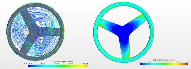
Computational simulations studies using Star CCM+ to determine the drag on various types of wheel designs.
Aerodynamics: Before the start of the summer Todd focused on locking down the aerodynamic shape of the bike. With some help from Trefor’s custom optimization code (more on that later), the bike is designed for an extend laminar boundary layer, which means that the air in the thin layer next to the bike stays nice and smooth (with 5-10 times less drag) for 75% of the length of the bike. Later on in the summer the aero team will be focusing on turning wheel fairings, wheel enclosures and ventilation drag.
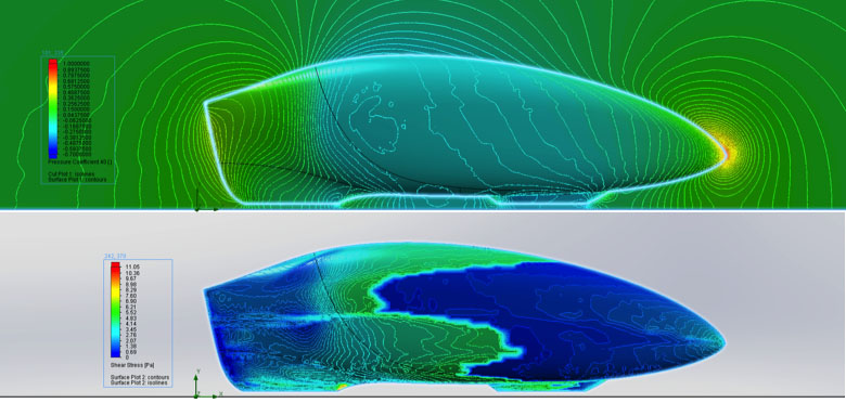
Top: Pressure Coefficient. Bottom: Skin Friction Drag. Aerodynamic analysis with SolidWorks Flow Simulation. Road testing from 2013 gave us confidence that we can achieve a laminar boundary layer to the point of minimum pressure (shown in the top picture with the darkest blue colour). Laminar flow isn’t easy to achieve or to simulate, but the picture below shows the difference in skin friction drag between the laminar and turbulent regions (where it jumps from blue to green).
Vision System: Once again the bike will be driven by camera vision, led by Alex, Aakash and Sean. Further development will go into extending the on-screen displays that Bluenose had to include pilot power, target speed vs. actual speed, distance down course and rpm.
Over the next few months you’ll be hearing from the various sub teams on the status of their design as we go from sketches to CAD models to testing it all out on the road! Stay tuned.